We can use water sensor to measure water level, water leakage and rainfall etc. This sensor is easy to use and hook with Arduino.
Hardware Overview
There are 10 traces or lines on the sensor, five of them are power traces and rest of them are sense traces. Sense traces are mounted between two power traces means after every power trace there is one sense trace available. These traces are not connected but bridged by water when submerged.

There is a power led and lights up when the sensor ON.
How Water Level Sensor Works?
These parallel conductors acts as a potentiometer whose resistance varies according to the water level. When resistance is small it means water level is HIGH and resistance higher means the water level is LOW.

The sensor gives an output voltage according to the resistance and we will calculate water level according to the resistance.
Water Level Sensor Pinout

S (Signal) goes to the analog pin you can connect to any analog pin.
+(VCC) goes to the Arduino digital pin. These sensors are very sensitive and only bear voltage from 3 to 5V. When the sensor is always on its life time goes down. So to overcome the problem we connect this to digital pin and we can turn on it when we need to get reading.
– (GND) is a ground connection.
Wiring Water Level Sensor with Arduino

// Sensor pins
#define sensorPower 7
#define sensorPin A0

// Value for storing water level
int val = 0;

void setup() {
	// Set D7 as an OUTPUT
	pinMode(sensorPower, OUTPUT);

	// Set to LOW so no power flows through the sensor
	digitalWrite(sensorPower, LOW);

	Serial.begin(9600);
}

void loop() {
	//get the reading from the function below and print it
	int level = readSensor();

	Serial.print("Water level: ");
	Serial.println(level);

	delay(1000);
}

//This is a function used to get the reading
int readSensor() {
	digitalWrite(sensorPower, HIGH);	// Turn the sensor ON
	delay(10);							// wait 10 milliseconds
	val = analogRead(sensorPin);		// Read the analog value form sensor
	digitalWrite(sensorPower, LOW);		// Turn the sensor OFF
	return val;							// send current reading
}
Water Level Sensing Basic Example
After uploading sketch check the result on the serial monitor. When the sensor is dry there should be zero value on the serial monitor. Then put the sensor in the water and notice what happened.

Here the point to be notice that the sensor should not be totally merged in water. You should only merged the exposed traces of the sensor.
Code explanation
First of all we define the power and signal pin of sensor. Then define a variable to store value of sensor.
Now in void setup section, we declare power connection as output and initialize as LOW. We also begin Serial with baud rate of 9600.

Then we call readSesor function to read the value. The sensor turns on for 1 minute and reads value and return it as analog values.

Sensor Calibration
We recommend you to calibrate sensor first to get accurate values. As we know that pure water is not conductive. The water is only conductive because of the minerals and impurities in it. So because the sensor is sensitive according to the water that you are using. Before actual using of sensor you have to notice values of sensor when sensor is dry, when sensor is partially submerged and when sensor is totally submerged.
Now you can set threshold or conditions according to the values that you are getting.
Water Level Sensing Project
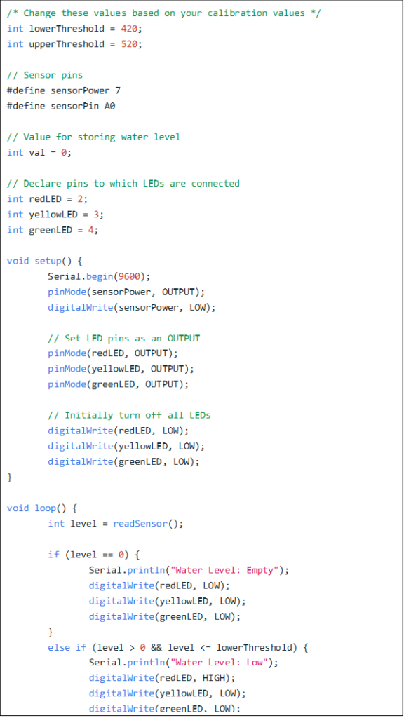
In this project we are going to read sensor value and apply conditions that below lower conditions will turn our red led and above higher condition will turn on our yellow led and between these conditions will turn on green led.


