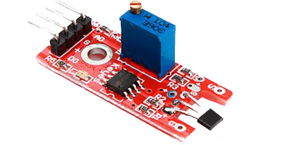
Hall effect sensor is a digital sensor. It is use to detect the magnet. When you came the magnet near to Hall effect sensor, it outputs a HIGH (5V) voltage to its Vout pin. In this tutorial, we will learn how to read value of Hall effect sensor with Arduino. It is basically used to calculate the RPM of motor etc.

Components :
- Arduino Uno
- Jumper Wires
- Bread Board
- Hall effect sensor
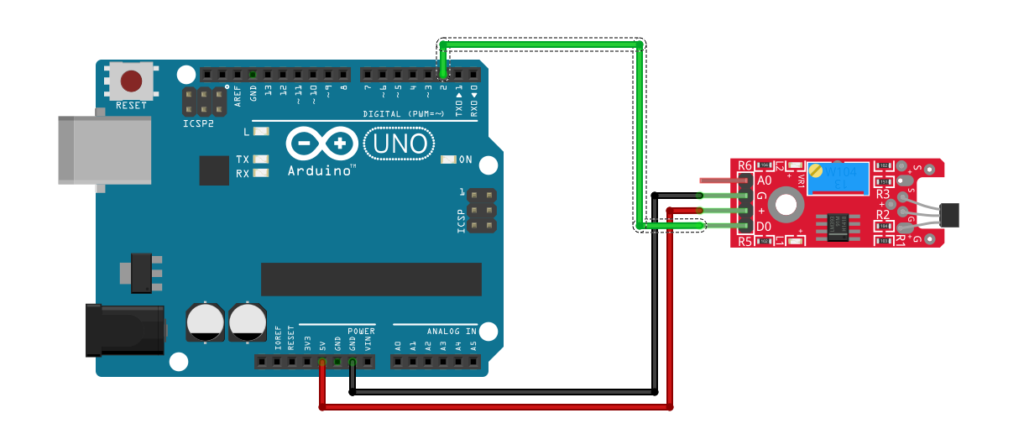
Pinout :
VCC –> VCC
GND –> GND
DO –> D2
Circuit Diagram :

Code :
// constants won't change. They're used here to set pin numbers:
const int sensorPin = 2;     // the number of the Hall effect pin
const int ledPin =  13;      // the number of the LED pin

// variables will change:
int buttonState = 0;         // variable for reading the Hall effect status

void setup() {
  // initialize the LED pin as an output:
  pinMode(ledPin, OUTPUT);
  // initialize the Hall effect sensor pin as an input:
  pinMode(sensorPin, INPUT);
}

void loop() {
  // read the state of the Hall effect value:
  buttonState = digitalRead(sensorPin);

  // check if the magnet is near to sensor. If it is, the buttonState is LOW:
  if (buttonState == LOW) {
    // turn LED on:
    digitalWrite(ledPin, HIGH);
  } else {
    // turn LED off:
    digitalWrite(ledPin, LOW);
  }
}


Good day! I just want to offer you a big thumbs up for your excellent information you have got here on this post. Ill be coming back to your blog for more soon.