This project focuses on developing a Virtual Production Studio, where cameras are controlled via IoT technology. The system integrates various hardware components such as ESP32, limit switches, three stepper motors, and motor drivers, and is managed through the Blynk IoT app. The setup allows for precise control over camera positioning, enhancing the production process with automation and remote access capabilities.

Components used in the Project:
ESP32 Microcontroller:
- Role: Acts as the central processing unit for the system, managing communications between the motors, limit switches, and the Blynk app.
- Features: The ESP32 is a powerful microcontroller with built-in Wi-Fi and Bluetooth, which facilitates easy integration with the Blynk IoT platform for remote control.
Stepper Motors:
- Number: Three stepper motors are used.
- Function: Each motor controls a different axis or movement of the camera (e.g., pan, tilt, and zoom).
- Precision: Stepper motors are chosen for their precise control over rotation angles, which is crucial for accurate camera positioning.
Motor Driver:
- Purpose: The motor driver provides the necessary current and voltage to the stepper motors. It interfaces between the ESP32 and the stepper motors, converting control signals into motor movement.
- Type: A suitable motor driver (e.g., A4988, DRV8825) is selected based on the power requirements of the stepper motors.
Limit Switches:
- Role: Limit switches are used to define the boundaries of the camera’s movement, preventing the motors from driving the camera beyond its physical limits.
- Operation: When the camera reaches a limit switch, the ESP32 detects this and stops further movement in that direction, ensuring safety and precision.
Blynk IoT App:
- Functionality: The Blynk app serves as the user interface for controlling the camera’s movements. It allows users to adjust the position of the cameras remotely via a smartphone or tablet.
- Integration: The app communicates with the ESP32 over Wi-Fi, sending commands to move the motors according to user inputs.
- Blynk IoT App:
- Functionality: The Blynk app serves as the user interface for controlling the camera’s movements. It allows users to adjust the position of the cameras remotely via a smartphone or tablet.
- Integration: The app communicates with the ESP32 over Wi-Fi, sending commands to move the motors according to user inputs.
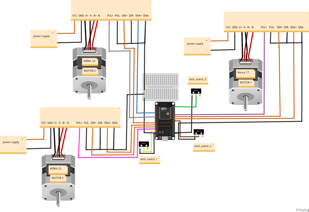
Circuit Diagram:

Working of Project:
Initialization:
- The ESP32 initializes the system by setting up the Wi-Fi connection and establishing communication with the Blynk app.
- The stepper motors are calibrated to their initial positions using the limit switches as reference points.
User Control via Blynk App:
- The user opens the Blynk app and connects to the ESP32.
- The app provides a control interface where the user can input desired camera positions (e.g., pan left, tilt up, zoom in).
- These inputs are sent as commands to the ESP32.
Motor Control:
- Upon receiving a command, the ESP32 processes it and determines the necessary movements for each stepper motor.
- The motor driver then actuates the motors accordingly, moving the camera to the desired position.
- Throughout the movement, the ESP32 monitors the limit switches to prevent overextension.
Feedback and Monitoring:
- The system can be designed to provide feedback to the Blynk app, such as the current position of the camera or any errors in movement.
- This feedback loop ensures that the user is always aware of the camera’s status and can make real-time adjustments as needed.
Code:
#include "BluetoothSerial.h"

#if !defined(CONFIG_BT_ENABLED) || !defined(CONFIG_BLUEDROID_ENABLED)
#error Bluetooth is not enabled! Please run `make menuconfig` to and enable it
#endif

BluetoothSerial SerialBT;


#define BLYNK_TEMPLATE_ID "TMPLlu3Ug1C_"
#define BLYNK_DEVICE_NAME "3 Axis Stepper"
#define BLYNK_AUTH_TOKEN "cvw9-cue2CD6Ifm7FpLjgmeXuqu8yf-m"

#define BLYNK_PRINT Serial


#include <WiFi.h>
#include <WiFiClient.h>
#include <BlynkSimpleEsp32.h>

char auth[] = BLYNK_AUTH_TOKEN;

// Your WiFi credentials.
// Set password to "" for open networks.
char ssid[] = "AHMED";
char pass[] = "11223344";


#define ena1 18
#define dir1 19
#define step1 21

#define ena2 34
#define dir2 26
#define step2 32

#define ena3 27
#define dir3 14
#define step3 12


int ln=1;
int ln1=1;
int ln2=1;


int virtualbutton;
int virtualbutton1;
int virtualbutton2;
int virtualbutton3;
int virtualbutton4;
int virtualbutton5;

bool motor1_right=false;
bool motor1_left=false;
bool motor2_right=false;
bool motor2_left=false;
bool motor3_right=false;
bool motor3_left=false;

int SPEED=2000;      //
int DELAY=1000;
int x=0;
int x1=0;
int x2=0;
int Step1=3000;    //motor 1
int Step2=2600;     //motor 2
int Step3=1000;     // //motor 3
//--------------------------------btn 1
int Step4=3000;       //motor 1
int Step5=3000;        //motor 2
int Step6=3000;         //motor 3
//--------------------------------btn2
int Step7=3000;          //motor 1
int Step8=3000;           //motor 2
int Step9=3000;            //motor 3
//--------------------------------btn3
int Step10=1000;
int Step11=1000;
int Step12=1000;
//--------------------------------btn 4
int Step13=1000;
int Step14=1000;
int Step15=1000;
//--------------------------------btn 5
int Step16=1000;
int Step17=1000;
int Step18=1000;
//--------------------------------btn 6


int LIMIT_SWITCH_1=13;
int LIMIT_SWITCH_2=5;
int LIMIT_SWITCH_3=23;

 char data;
Applications:
Film and Television Production: The system can be used in studios to automate camera movements during filming, reducing the need for manual adjustments and allowing for more complex shots.
Live Streaming: For live events, the system enables remote control of cameras, allowing operators to adjust camera angles without being physically present.
Virtual Reality (VR) Content Creation: Precise control over camera positioning is essential for creating VR content, where slight changes in perspective can significantly impact the viewer’s experience.


